Showing posts with label haptic glove. Show all posts

Saturday, 11 October 2014

Integration of Subsystems on the Software level

This post we will be talking about integrating the all subsystems on software level. As a whole, we are using 3 arduino boards.
                                Board 1 - Robot Arm and Hand
                                Board 2 - IR Sensors on the Robot Hand
                                Board 3 - Glove (Vibrational Motors)

Shown is the overview of how the user control the robot remotely. Setting up the server is discussed in detail here.
Figure 1 - Overview

A note on vibration

From this previous post, you can see the IR data that is being sent from the Arm Server to the User Server (previously named Client). The data that was being received looked a little like this:


This data is essentially what the vibrational motors are using to determine their strength. I have used 3 levels for haptic feedback, but it is possible to use more. The vibration motors we purchased can draw approximately to 60mA at 3V (recommended operating range 2.5-3.5V) - which is perfect for Arduino ports that output 3.3V.

Experimentally, the tactility that you can sense in your fingers is not particularly sensitive. A change from 2.9-3V is negligible. As such, you don't need to perfectly map the proximity of the sensor with the vibration motors (which was an initial idea we investigated). To make sure we didn't have to send masses of data along the WebSocket, we determined that 3 varying levels of  vibration was an optimal amount. This may change with proximity sensors that sense at differing distances, but the levels we have allow a bigger difference in tactility.

There is some research with tactility, but it is mainly concerned with a) medical/orthopaedic benefits of using vibration gloves, b) difference in sensing tactility at difference frequencies or c) the limits of hand tactility. For our purposes, the frequency study is of most interest, but in essence our determination of the levels was done experimentally.

For completeness, the spec sheet for the motors state that there's a 12000 RPM at 3V which translates to 200Hz, as 1Hz = 60 RPM. The IEEE article linked above shows that a maximum tactility at around 250Hz, which the most sensitive region being 80-120Hz.

The level that you can read from the Arduino analog pin ranges from 0 to 255. The levels I have used move from a level of 64- 128 - 255; ie quarter value - half value - full value. Assuming a linear change of RPM, this would translate to approximately 50Hz - 100Hz - 200Hz.

Experimentally, any slight buzzing can just be sensed. The first level does not necessarily need to be at a level of 64, but it is an easy fraction of the full value. The change up to the second value is a noticeable difference, and the highest value buzzes like no tomorrow!

We felt that if it was 15cm or further, it should just be able to be sensed. Obviously, if it's right next to the sensor it should be buzzing quite strongly. As such, there must be an intermediate value between them, otherwise you would be stepping up too quickly.

In the future, there may be more research done on the number and strength of the levels of vibration. However, at this time, we do not think it is necessary.

Next up - integrations (not the calculus kind!)

Wednesday, 8 October 2014

Multi-boards and the curse of the vibration motors

Johnny-Five is the key Javascript Node Module that we are using in this project. Essentially, it allows Javascript to talk to the Arduino using a standard protocol called the StandardFirmata. You can check the documentation in the link above - it bundles up all the types of inputs and outputs you would need in a very easy-to-use manner.

However, the one problem you'll find with working with Open Source packages is that they'll change on you without notice, quickly and quietly. Furthermore, these packages do not always have your application in mind, and thus will not necessarily have documentation to support what you want to do! This blog post will detail some problems we had while using this package - but of course I should state that it's still an absolutely AMAZING package and we wouldn't be here without it.


Multiple Boards

One of the things Johnny-Five does not have very good documentation about is supporting multiple boards in one Javascript script. Here is the documentation they have; it is good for the application they have in mind, but not for our purposes. It seems that using the 
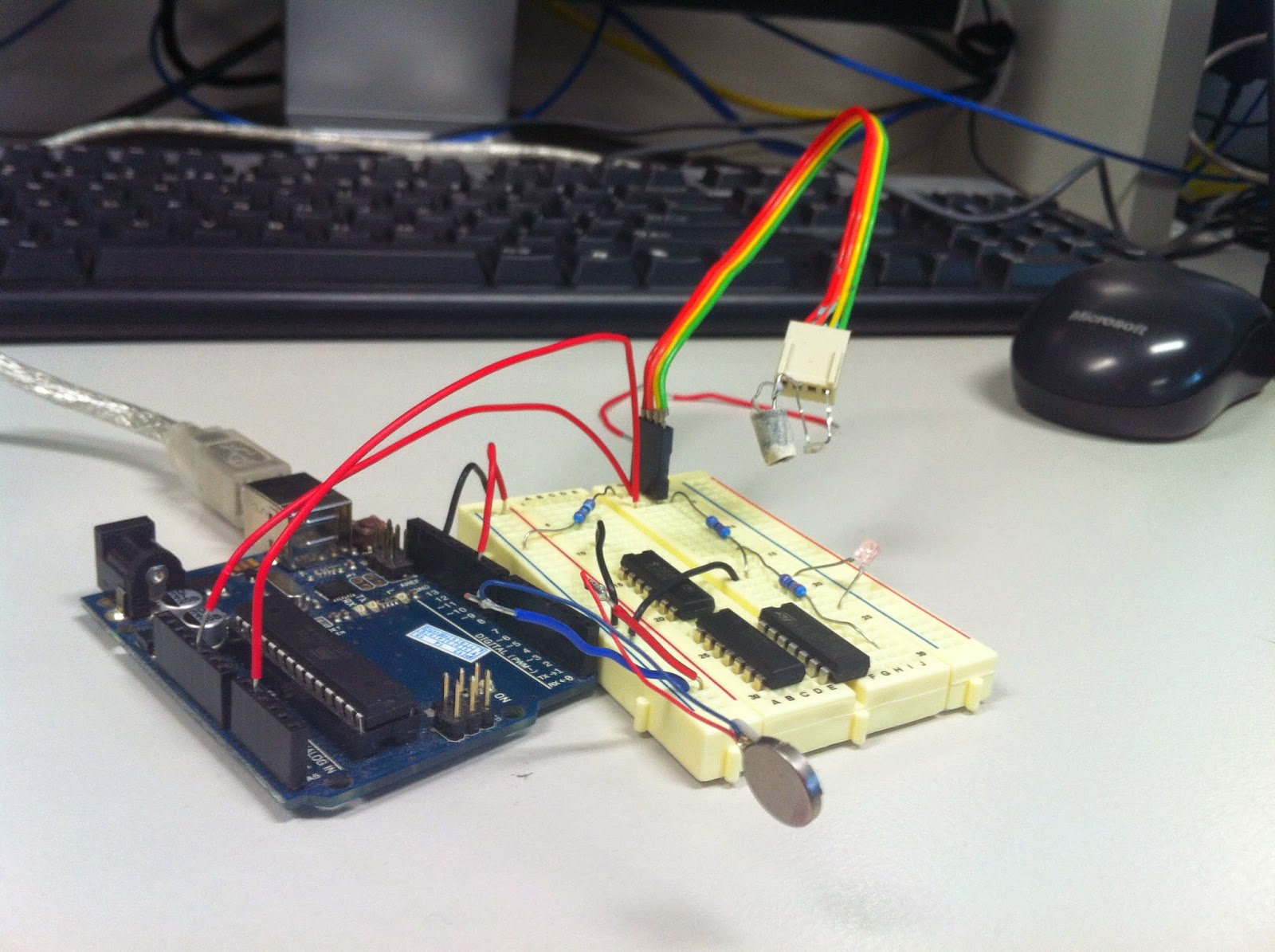
Boards object allows you to run the same code on BOTH the Arduino's, but not different code on each - which is what we'd like to do. The circuitry for control on the arm, and the IR sensors were on different boards. One uses an Arduino MEGA, one uses an Arduino UNO. (The vibration motors also use an Arduino UNO, but at this time we were just focussing on the 'server-side' system).

The problem was exacerbated by the fact that the laptops Ashan and I were using were different - a MAC and a Windows laptop. Thus, every time we tried to experiment with the same code, we'd have different results.

See below for the different ways you can go about making multiple boards according to the documentation

The first method is an automatic method of acquiring the devices. However, this doesn't guarantee you'll get the same one each time. We tried this, and it did not always assign the correct board.

The second method assigns the ports correctly, but because of the way the class is created in Johnny-Five, it does not allow you to control the boards separately. The third way outlined above is highly similar to the second way.

The actual solution that is MUCH easier is as follows:
1. Create different board objects
2. Make sure that the objects you create are assigned to the board

Each object that is created is given a 'board' property that relates to which board it is attached to. This feature is not in the actual documentation for each of these things - I just hoped that it would be an exposed property of the object, and it was!

Thus, our problem with the documentation was solved. We could use multiple boards in our Javascript programs!


IR Communication Issues

When we decided to try and use the server-client relationship to communicate between Arduino boards (more specifically, the IR sensors and the vibration motors), a problem arose.

Namely, the IR sensors were going WILD! Sometimes they would read a consistent value, but for a majority of the time, they would wildly fluctuate between the actual value, and half the actual value. This is the weirdest behaviour I've ever seen, and I started troubleshooting the damn IR sensors.

- the connections were stable - I tested them individually with a separate Arduino and they were giving the right value
- the program itself was fine - I tested the IR sensors isolated on one computer, and the readings I was getting were fine.
- I tried it on both mine and Ashan's laptops, and it worked! It was only with a CLEAN INSTALL on the lab computer that it would fail! WHY!

This testing stage was the most infuriating part, as I could not isolate the problem. But I finally found the solution...

Checking the documentation of the johnny-five website, I found that only recently had documentation changed in how you would access data from a sensor. The reason it was working on both our laptops but not a CLEAN INSTALL is that we had an older version of the package on our computers.


The top part of this code shows how you read from the sensor in an earlier version. The bottom part of this code shows you the NEW way to read from the sensor. This was not reflected as a change anywhere that I could find, and the documentation did not reflect that there had been any change at all! The code was just different - I thought I was going crazy!

This change was able to fix the bug. The lesson we learnt here is that using Open Source packages has it's detriments - namely, that whoever is maintaining the code may not be the clearest about their changes.

Damn it Johnny-Five...


U mad bro?

The beauty of Infra-Red over a WebSocket

This post will outline the new IR sensors we have built, problems we faced during it, and the integration of them with software.

Hardware

The initial IR sensors we built were cheap and dirty (figuratively, of course). Using an all-purpose photo-transistor turned out not be a good idea. It would pick up far too much ambient light and thus wherever we went, the phototransistors would be affected a non-trivial amount. This would make it quite hard to decide what levels of contrast we would need in our software.

Furthermore, the IR sensors were affected by the type of material (more importantly, the colour) and how far away each thing was. For example, this system does not work well with black objects. It is one of the limitations that also applies for the Leap Motion; it is the limitation of Infra-Red itself - that it is absorbed by black objects so well!

Thus, I examined some other types of sensors we could use. The first idea I researched was whether you could modulate the signal coming from the IR LED and have it receive at a certain wavelength so that each finger's sensor wouldn't interfere with each other. To this end, I found a receiver called the TSOP4838, which recieves the signal at around 37kHz. Modulating the light of the LED to 37kHz was not difficult - it was a very simple RC circuit (I also experimented using a function generator at 37kHz).


However, to my dismay, I found that the output of this TSOP was digital in nature. It would go HIGH or LOW, but would not output an analog value. This would not be useful for our purposes, as the sensors would need to give a different analog value based on how far away an object was. Interestingly, I found out that these TSOP receivers were more generally used for remote control systems and thus had a long range. I was able to pick up the signal of this modulated LED from quite a fair distance - maybe 60-100cm. The LED I used has quite a narrow view angle, and I was surprised it would be able to pick it up. In the end, I probably could have worked out a solution using the TSOP's, but instead I hit on a much simpler idea.

Infrared Phototransistors: They essentially work the same as the phototransistors we were using before, but instead have a built-in filter for Infra-Red light! This allowed the software to be changed very minimally, and a much more accurate level to be given. A note on the IR phototransistors and the IR LEDs - they have quite a low viewing angle - around 15 degrees. Thus, the IR sensors are highly directional. In the future, it may be valuable to install LEDs with a higher viewing angle, or install more of these sensors so more parts of the hand can have haptic feedback.

The circuitry sketches are shown below:


This sketch shows the basic idea of the phototransistor circuit


The top half of this drawing is the ideas behind how to actually build the VeroBoard for this sensor and how small I could make it.

The final product is below! Shen will detail more about the integration of the sensors and the fingers in another post - suffice to say that these turned out quite well!


The only problem with these sensors is that they were not identically made. Even the slightest difference in the heights of the phototransistor and the LED would cause a much different reading. The angle of each LED and phototransistor determines the optimal distance that it can measure. The next section will detail the software readings and problems that came with the IR sensors.


Software

In an earlier post, I detailed the way that the Arduino would work in reading the IR data. The polished version in Javascript is below:

The levels that I have chosen have been experimentally determined. I decided that a 15-10cm, 10cm-3cm and 3cm-0cm threshold should be used. This was an arbitrary decision, but it gave what I felt to be the right amount of distance for a change to occur. If the lowest threshold was longer than 15cm, then it would start vibrating too early. This is what occurs in the checklevel() function in the above code - it outputs a certain level from 0-3 on the intensity of the vibration (a later post will detail the software of the motors).

Using Arduino code, the following values were recorded when there was nothing in front of the IR sensor:
Thumb: 9
Index: 5
Middle: 8
Ring: 10
Pinky: 5

The thresholds you see in the above code come from using a white sheet of paper at differing distances away from the front of the IR sensors. This gives the best response; using other colours will give varying responses (ie the distance thresholds will be slightly different), but it works well with a variety of objects as will be shown in a later demo.

The reading of the sensors comes from each of the small sections that start with "Finger.on('data'...". As NodeJS is asynchronous, as soon as there is data that can be read from the finger, it will be taken and used to update the 'levelarray' that contains the intensity of response for each finger. The reason it is so small is that I felt it would be easier and quicker to send 5 numbers over the socket than a fluctuating array. It is a small difference but it turns out to be easier to do anyway.

Below is what you receive on the client-side:


You can probably see when we introduced an object in front of the fingers, and when we took it away! Another thing you will see is that the fingers are not always consistent in their reading - this is due to the asynchronous nature of the calls that are quite sensitive to change. It does not affect the use of the system, however, and thus does not cause a problem.


Coming soon: vibration motor software integration and fixing wiring problems

Friday, 6 June 2014

Presentation Day!

Yesterday we had to present what we had done in front of our supervisor, Jonathan Li. Andy Russell was secondary supervisor while Geoff Binns and a dozen other friends were there to support us.

We had four demos we wanted to show.

1. Mentor Arm responding to commands from the keyboard

2. Haptic feedback from proximity IR sensors

3. Robot Hand responding to hand gestures via Leap motion

4. Invisible wall - Haptic feedback and Leap motion

The demos went really well. There were some glitches here and there however the overall response was positive!

If you missed our presentation, here are the slides:


Friday, 16 May 2014

Bzzt! Bzzt! BZZT!

After the arduous long journey, waiting for the vibrational motors to arrive at Monash University, toiling with Ray in finding a new supplier after the old one took a MONTH to tell us they weren't sending them, we FINALLY got some vibrational motors!


Little Bird Electronics were a little more expensive, but they were able to ship within a day! Next time we'll have to look a bit harder and care a little less about price I think!

Here below, we have some of the first, ugly prototypes of the haptic feedback system working. The first figure is the ramshackle IR sensor for proximity (which will probably change), and the second is the motor in action! Or as 'in action' as can be seen in a stationary picture.


See below the whole set up. The IC's aren't actually part of the breadboarding, they're just...there. This set up was able to give graded haptic feedback at distances of 3cm from the lab table. The main problem is, again, the reflectivity of surfaces and how IR light is reflected. On different materials and different colours, the sensor feedback is different, and currently, requires a manual calibration to get meaningful graded feedback. I will be looking into ways to automatically calibrate the IR sensor, or possibly just use an series of high-power LEDs to illuminate objects.


Verifying that the prototype was functional, I made sure to create the motors as they would be on the glove when I procure one. As you can see below, it looks like the tendons of a hand, or maybe the nervous system you'd expect on a hand! (totally unintentional) Thanks must be given to Ray as to the connectors for the Veroboard :)


The next things to do will be, after the hand issue is sorted out, mounting the motors on a glove, and mounting the proximity sensors on another. Here's hoping for greater progress!

Friday, 4 April 2014

Short update on the IR sensing equipment

Hey all! It's been a while - mostly due to the fact that my subsystem is waiting on the most important parts - VIBRATIONAL MOTORS!

We've purchased them from a US company, but there were a couple of complications in the purchasing bureaucracy that has led their shipping to be delayed. In the mean time, though, I've been learning JavaScript for use in NodeJS, which is what we'll be using in the LeapMotion interface. The source I have been using is Eloquent Javascript, quite a useful resource, and I'll be moving on to Node soon enough :)

Furthermore, I've been prototyping the infrared ("IR") sensors that Ray had left over from some design units from the last couple of years. These work quite well in terms of voltage - an Arduino can easily deal with them. However, there were problems we encountered in the process.

Firstly, the IR emitter itself is not strong. The receiver was not able to pick up the response from it very well. Instead, we substituted an IR LED. This was able to give a much stronger response that we could read from the Arduino. Next, the ambient light of a room can affect the response, and thus needs to be taken account in the code. Lastly, the colour of the object being put in front of the sensor matters as well - black is not a good colour for IR sensing as it absorbs so much of it!

Thus, we used a bit of a hack to work out if it was close to something or near something. See the short code snipped below:

#define IRreceive A1 
int IRinitial;
void setup() { 
Serial.begin(9600); 
pinMode(IRreceive, INPUT); 
delay(100); 
IRinitial = analogRead(IRreceive); 


void loop() { 
long IR; IR = analogRead(IRreceive);
 Serial.print("NUMBER: ");
 Serial.println(abs(IRinitial - IR)); 
}

The initial read of the IR sensor is used to assess the ambient light of the room. This is then used to compare to response we receive from the sensor. The response to most colours is usually higher. However, for black, it does not sense that it has been put close to the IR receiver until it is pretty much covered - in which case it will give an even lower response. Thus the need for the in abs the code.

Once the motors have come in, I'll be working on making these IR sensors send information to them and hopefully emulate some sort of haptic feedback.

Tuesday, 18 March 2014

Hectic Feedback!


Part of the AirGrip project is to create a pair of gloves, namely the HUMAN GLOVE and the ROBOT GLOVE. The 'human glove' sends signals to the user via haptic feedback while the 'robot glove' contains sensors that can detect obstacles. We have actually made this one of our sub-projects (one of the three). Read more about the division of the project in a earlier post: link

Last Friday we took apart old mobile phones to locate its vibrational motors (link) to be tested as haptic feedback.  Unfortunately we were not so lucky with it. But that didn't stop us there!

After browsing through some websites, we've found some online shops who sells vibration motors ranging from 1.5V to 10V! We have also found that piezoelectric speakers, at an optimum frequency are a plausible alternative. 

First we have the Eccentric Rotating Mass (ERM) Vibration Motors. Below is an example of one such product call 'pico vibe' by Precision Microdrives. Images taken from: link


The same online store also stocks Linear Resonant Actuators (LRA) Vibration Motors. We are actually in the process of ordering one of these to test out how suitable it is for our glove. More specifically, the Precision Haptic 10mm Linear Resonant Actuator - 3.6mm type: link


Lets take a look whats INSIDE a LRA vibration motor. Image taken from: link
Before our sample arrives, we have been playing around with the Piezoelectric speakers. At around 150hz and supply voltage higher than 3V, we can generate a low frequency buzzing noise but also felt on the finger! We broke the cover to isolate the piezo from the plastic casing. 

We used an Arduino to generate a square wave at a specific frequency with the 'tone()' function which also allows us to control multiple Piezos. One advantage was the low current and low power usage. However, the vibrations was weak but strong enough to 'feel' and know that it is there. 

So we have to decide... LRAs or Piezos! 

Stay tuned ... for the verdict!

Friday, 14 March 2014

A mission for vibrational motors

Being the highly resourceful group that we are, we were able to procure some mobile phones in the hopes that we could extract the vibrational motors from the circuit boards and use them in our haptic feedback for the glove.

As you can see below, toothpicks are the tools of champions to open up mobile phones :D


The idea was that if we were able to get them cheaply, we could use them to great effect in our prototype glove. However, as you can see below...


It's very hard to identify what component is what. The speaker and microphone are easy to identify, but EVERYTHING ELSE is soldered down or inaccessible with normal tools.

Thus, this mission failed. Plan B will be incoming - piezo-electric speakers!