Previously (
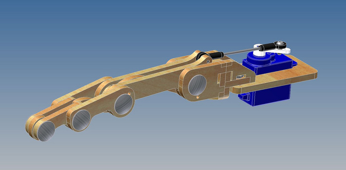
Link ) we found the Flexy hand limited and unsatisfactory to our needs. We foresee problems with the mechanism and decided to take a different route. In this post, we will explore a different mechanism as described in our presentation (Fig 1), namely linkages.
This mechanism contains
multiple rigid bodies fitted in a 4-bar linkage configuration. Previous work with linkages such as the Belgrade/USC hand (Fig 1) have two sets of 4-bar linkages (L1 and L2 as shown in Fig 2. and Fig 3. respectively) for each finger.
 |
| Fig 2. Linkage 1 |
 |
| Fig 3. Linkage 2 |
The entire finger is controlled by one actuator via a crank mechanism (Fig 4). The crank mechanism effectively transforms a circular motion into a reciprocating motion (linear back and forward motion). The actuator would move in a circular motion about the z-axis. The motion would translate to a circular motion about the y-axis to manipulate L2 and L1.
.png) |
| Fig 4. Crank 1 |
This mechanical transmission has been quite popular since the availability and affordability of servos. Servos serve as effective actuators for this design.
We attempted to create our own hand based on the Belgrade Hand. We were also inspired by Roy's Fingers found
here (Fig 5).
 |
| Fig 5. Roy's Finger by Brian Roe |
We would first create a prototype out of paper, cardboard, sticky tape and some sticks as shown below. (We lost one of the stick and replace one of the sticks with a piece of wire)
 |
| Fig 6: Finger Close |
 |
| Fig 7: Finger open |
In our next post, we will show the 3D model we made with Google's Sketchup!


.png)


No comments:
Post a Comment